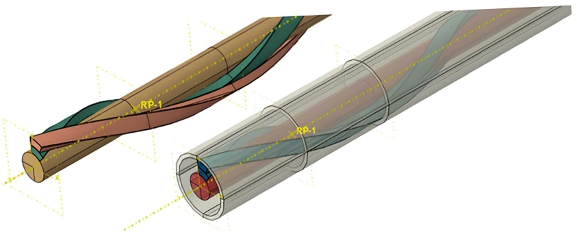
The design requirement
Helical reinforcement geometry needed to preserve the correct envelope, interlayer clearances and developed lengths. The project combined parametric CAD with consistent manufacturing documentation for cable components.
From models to drawings
Geometry was driven by radius, pitch, lay angle, strand diameter and strand count. Interfaces were assessed using worst-case and statistical tolerance stack-ups.
Detail drawings included dimensional and geometric tolerancing and were managed in Windchill PLM with bills of materials, revisions and change procedures. Creo and SolidWorks formed part of the technical environment.
Reported outcomes
The study states that updates previously requiring two to three days could be completed on the day a design change was decided. Drawing views referenced the same parametric master model.
Tolerance-stack checks identified two potential layer-clearance conflicts before prototyping. The released, configuration-controlled package provided manufacturing and quality with a shared technical definition.
What this case demonstrates
3D CAD connects interfaces, tolerances and production documentation. This continuity helps prepare prototypes, update assemblies and organise technical discussions with suppliers.
Methods for your project in Morocco.
Explore the related services and discuss the scope suited to your equipment.
Mechanical designIndustrialisation & reliability